Motivation
In a previous post, we learned the theory behind Wheatstone bridges and how we could use them to interface with RTDs. Our next step is building something useful with temperature data, a task that microcontrollers are well-suited for. Despite their versatility, microcontrollers face unique resource constraints; as embedded engineers, we can overcome these constraints by offloading some functionality to hardware.
Let’s consider how to send temperature sensor values from an analog-to-digital converter (ADC) to a serial transceiver. The naive approach involves polling the ADC and sending the value to the transceiver inside the main loop. Thus, if we want to increase the throughput of sending temperature sensor data, we need to minimize the number of instructions running inside the main loop, preventing us from handling other tasks inside the loop. Through direct memory access, we can build a more efficient solution.
Like any embedded development task, there are multiple plausible solutions, and the optimal choice depends on additional requirements. Direct memory access requires significant setup overhead, meaning that it is unnecessary for sending individual values.
Hardware Setup
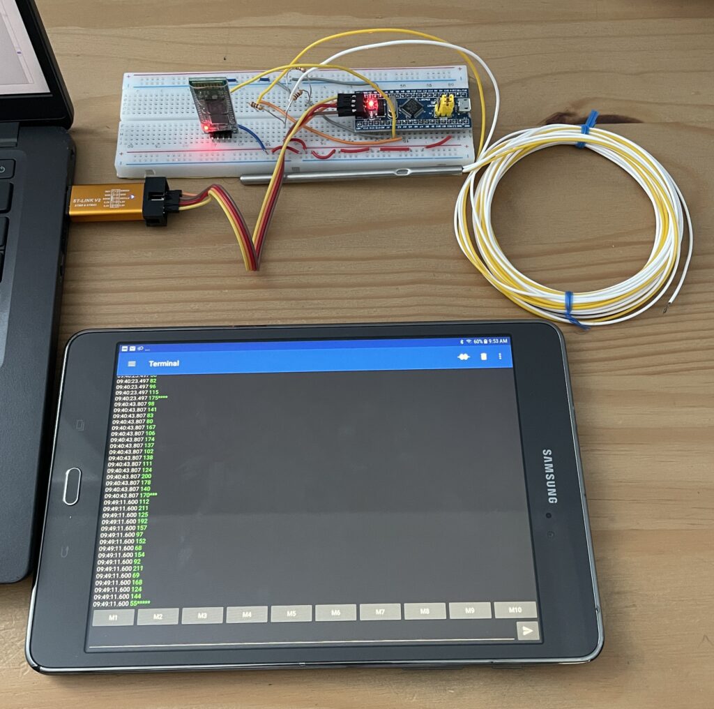
This post builds on the RTD Wheatstone bridge circuit from earlier. The new additions are the HC-06 Bluetooth module, which communicates over UART, and the STM32 “Blue Pill” development board. The RX pin of the HC-06 is connected to PA2 (USART2_TX), while both terminals of the Wheatstone bridge are connected to PA0 and PA4 (ADC1_IN0 and ADC1_IN4, respectively).
To develop the firmware, I used the STM32 CubeIDE with ST’s hardware access library (HAL). CubeIDE automatically generates boilerplate code for peripherals. To visualize the Bluetooth data, I used the Serial Bluetooth Terminal for Android.
ADC Setup
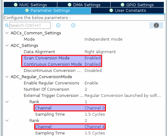
Because we’re reading two ADC channels on ADC1, we need to use scan conversion mode. This mode permits custom scanning orders and scanning rates without having to reset the ADC after polling each channel. Additionally, we set the rank of channels 1 and 4 to ensure that the ADC polls both channels.
UART Setup
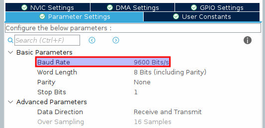
We use asynchronous serial communication to transmit data via the Bluetooth module (a synchronous implementation would require a third clock signal). The important factor here is the Baud rate, or the number of bits transmitted per second. The HC-06 module communicates over 9600 baud.
Clock Setup
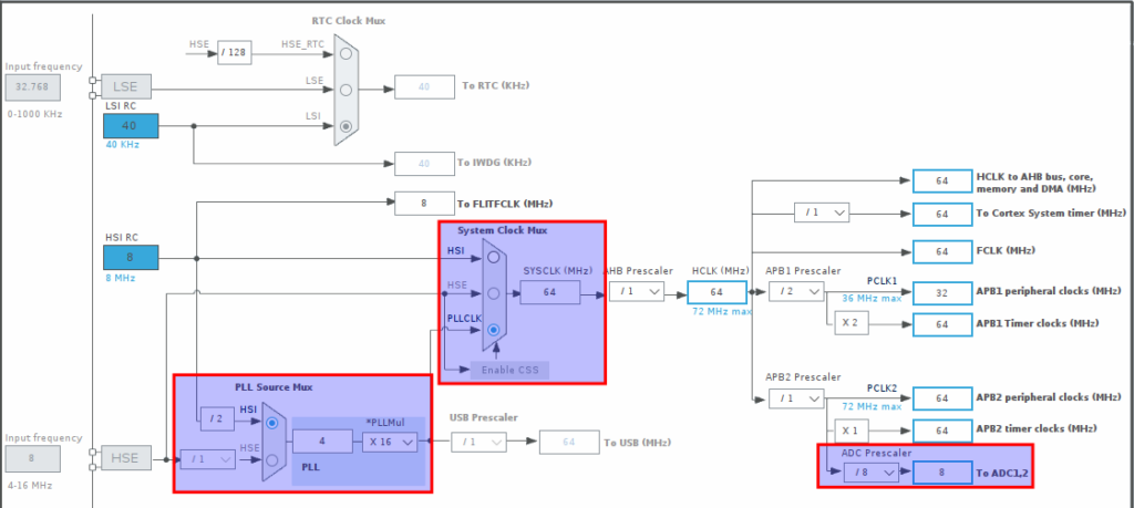
Like most sophisticated microcontrollers, the STM32 offers extensive clock configuration options. Initially, I kept the system clock (SYSCLK) at the default of 8 MHz, but I noticed that my ADC callbacks weren’t being called. According to this StackOverflow thread, the system clock needs to be raised higher to detect when the DMA buffer is fully populated. Thus, I used the STM32’s phase-locked loop and SYSCLK multiplexer to raise SYSCLK to 64 MHz. Because the ADC clock requires 14 MHz or less, I scaled SYSCLK down by a factor of 8 to run the ADC at 8 MHz.
Implementation
Our logic will be as follows:
- Include the
HAL_ADC_ConvCpltCallback()ADC callback in our code. This callback is triggered every time the multichannel ADC scan finishes writing 16 sets of values (32 total) to the configured DMA buffer. Compute the voltage difference between the terminals of the Wheatstone bridge and write the result to one of two alternating UART transmission buffers.- Because the UART interface takes longer to transmit data than the ADC takes to poll the analog inputs, using two buffers avoids race conditions. If we used one buffer, then the ADC might overwrite the data currently being transmitted.
- Manually request the DMA peripheral to transmit the values in the current transmission buffer through the UART interface.
- Manually trigger the next ADC conversion.
Based on this description, we would expect the following sequence of transmission buffer writes. The buffer that’s being written to and the buffer that’s being transmitted are maintained in separate state variables.
HAL_ADC_ConvCpltCallback() Execution 0
- Write the computed voltage differences to transmission buffer 0.
- Begin transmitting buffer 0 through UART.
HAL_ADC_ConvCpltCallback() Execution 1
- Write the computed voltage differences to transmission buffer 1.
- If the UART interface is busy, allow it to complete buffer 0 transmission. Otherwise, transmit buffer 1.
HAL_ADC_ConvCpltCallback() Execution 2
- Write the computed voltage differences to transmission buffer 0.
- If the UART interface is busy, allow it to complete buffer 1 transmission. Otherwise, transmit buffer 0.
Seasoned embedded engineers might recognize that a similar algorithm can be implemented using a circular buffer and half-complete and fully-complete callbacks. That is a workable solution to avoid race conditions: When the half-complete callback is invoked, UART can begin transmission of the first half of the DMA buffer. While the UART transmission completes, the ADC can write values to the second half. The advantage of this approach is that ADC conversions do not need to be manually triggered; however, troubleshooting race conditions becomes more challenging.
DMA CubeIDE Configuration
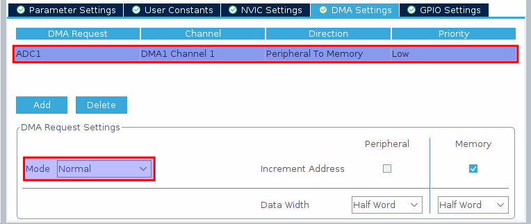
In CubeIDE, we configure ADC1’s DMA interface to transmit data from Peripheral to Memory and implement a Normal buffer. If we used the half-complete and fully-complete ADC DMA callbacks as suggested in the last section, we could have implemented a Circular buffer.
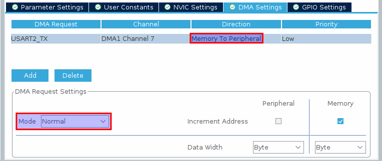
Additionally, we configure the transmit channel of USART2 to use DMA through a Normal buffer. Notice that the direction is Memory to Peripheral: If we configured the RX channel, we would use Peripheral to Memory DMA, like the ADC.
Some online sources indicate that this configuration is sufficient; however, I also had to enable ADC1 and ADC2 global interrupts and USART2 global interrupt in the Nested Vectored Interrupt Controller (NVIC). 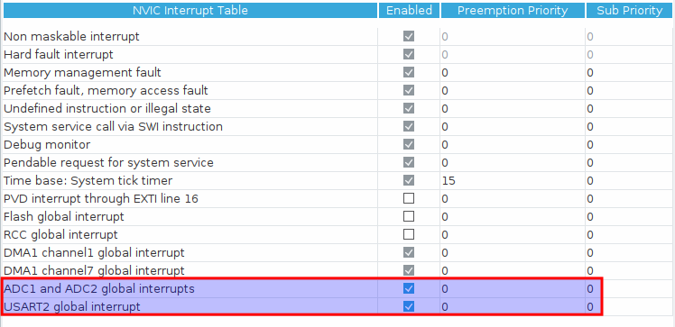
stm32f1xx.c. Neglecting these IRQ handlers, which often reset important flags, is a challenging problem to detect.
extern DMA_HandleTypeDef hdma_adc1;
extern ADC_HandleTypeDef hadc1;
extern DMA_HandleTypeDef hdma_usart2_tx;
extern UART_HandleTypeDef huart2;

void DMA1_Channel1_IRQHandler(void)
{
  HAL_DMA_IRQHandler(&hdma_adc1);
}

void DMA1_Channel7_IRQHandler(void)
{
  HAL_DMA_IRQHandler(&hdma_usart2_tx);
}

void ADC1_2_IRQHandler(void)
{
  HAL_ADC_IRQHandler(&hadc1);
}

void USART2_IRQHandler(void)
{
  HAL_UART_IRQHandler(&huart2);
}
Firmware & Testing
Because I’ve already shown my CubeIDE configuration, I’ll omit the peripheral configuration code from my snippet.
#define ADC_BUF_LEN 32
#define UART_BUF_LEN 81
ADC_HandleTypeDef hadc1;
DMA_HandleTypeDef hdma_adc1;
UART_HandleTypeDef huart2;
DMA_HandleTypeDef hdma_usart2_tx;
// These global variables must be declared as volatile
// Otherwise, the compiler may try to incorrectly optimize them
// The compiler is unaware that the callbacks are invoked by hardware
volatile uint16_t adc_buf[ADC_BUF_LEN];
uint8_t uart_tx_bufs[2][UART_BUF_LEN];
volatile uint8_t current_tx_buf = 0;
volatile uint8_t current_adc_buf = 0;
int main(void)
{
/* Reset of all peripherals, Initializes the Flash interface and the Systick. */
HAL_Init();
/* Configure the system clock */
SystemClock_Config();
/* Initialize all configured peripherals */
MX_GPIO_Init();
MX_DMA_Init();
MX_USART2_UART_Init();
MX_ADC1_Init();
HAL_ADC_Start_DMA(&hadc1, (uint32_t*)adc_buf, ADC_BUF_LEN);
/* Infinite loop */
while (1) {}
}
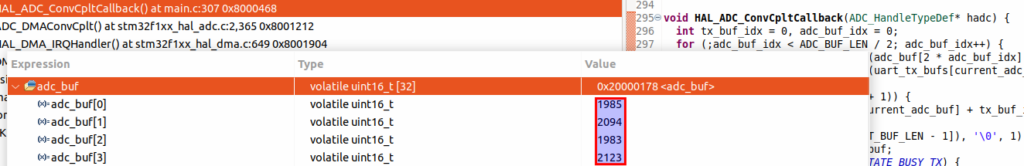
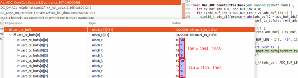
void HAL_ADC_ConvCpltCallback(ADC_HandleTypeDef* hadc) {
int tx_buf_idx = 0, adc_buf_idx = 0;
for (;adc_buf_idx < ADC_BUF_LEN / 2; adc_buf_idx++) {
uint16_t adc_difference = abs(adc_buf[2 * adc_buf_idx] - adc_buf[2 * adc_buf_idx + 1]);
tx_buf_idx += sprintf((char*)(uart_tx_bufs[current_adc_buf] + tx_buf_idx), "\n%d", adc_difference);
}
// Pad the buffer with "*" for a cleaner appearance on the Bluetooth terminal
if (UART_BUF_LEN > (tx_buf_idx + 1)) {
memset((char*)(uart_tx_bufs[current_adc_buf] + tx_buf_idx), '*', UART_BUF_LEN - tx_buf_idx - 1);
}
memset((char*)(uart_tx_bufs[UART_BUF_LEN - 1]), '\0', 1);
current_adc_buf = !current_adc_buf;
if (huart2.gState != HAL_UART_STATE_BUSY_TX) {
HAL_UART_Transmit_DMA(&huart2, uart_tx_bufs[current_tx_buf], UART_BUF_LEN);
current_tx_buf = !current_tx_buf;
}
// Manually trigger next conversion
HAL_ADC_Start_DMA(&hadc1, (uint32_t*)adc_buf, ADC_BUF_LEN);
}There are a couple important points to be aware of:
- Using the
volatilekeyword is critical. Declaring a variablevolatileforces the compiler to reload the value of the variable every time it’s used. In this case, we declare the DMA buffer, which is changed by hardware, and the buffer state variables, which are modified by a callback invoked from hardware, volatile. MX_DMA_Init()must be called before any peripherals that utilize DMA are initialized (i.e.,MX_USART2_UART_Init()andMX_ADC1_Init()).- For this simple example, the CPU idles in an infinite loop. We could implement useful functionality in the loop.
sprintf()returns the number of bytes written to thechararray. We keep track of the number of characters written across iterations of the loop to construct onechararray encoding 16 values.- We allocate both buffers in
uart_tx_bufsto hold 81 bytes. This is equivalent to 5 characters (newline character + 4 digits) * 16 + 1 (null terminator). Appending*withmemset()is purely for aesthetic purposes.
Let’s test our work in the debugger. Place a breakpoint inside the HAL_ADC_ConvCpltCallback() callback where the HAL_UART_Transmit_DMA() function is called. Start the debugger. When the breakpoint is reached, hover over values of interest. The first image depicts the raw values from the ADC, while the second image illustrates the built string inside the transmission buffer.